The Hulett Automatic Ore Unloaders Online
Magnetic Switch Controllers on Electrically-Operated Automatic Ore Unloaders at Lorain, O.*
By R. I. Wright, Assoc. Am. Inst. E. E., Sales Engineer, Electric Controller & Supply Co., Cleveland, O.
*Engineering News, v. 54, no.19, Nov. 9, 1905. New York: The Engineering News Publishing Company. pp. 481-483.
An article in Engineering News of Aug. 3, 1905, showed and described an installation of a new type of unloading machine, the Hulett Bucket-leg Ore Unloader, built by the Wellman-Seaver-Morgan Co., of Cleveland O., for the National Tube Co. at Lorain, O. These ponderous machines, whose primary object is to enable rapid and cheap unloading of large ore steamers, are operated in all their motions by electric motors, and depend for efficient action in no small measure upon the controlling apparatus by which the motors are directed. The following gives a brief description of the control equipment, with photographic views of some typical elements of the equipment.
An unloader of the Hulett type has the following motions: (1) Carriage travel, back and forth on the gantry bridge; (2) Carriage tilting, that is, bucket-leg hoist; (3) Bucket rotation (about a vertical axis); (4) Bucket closing and opening; (5) Travel of the auxiliary hopper-car at the rear of the machine, which takes ore from a hopper into which it is dumped by the unloading bucket, and elevates it to the stock pile; (6) Traverse of the entire machine on tracks parallel to the dock, and slewing the machine by differential motion of the two trucks. Each of these motions is performed by one motor. The motors are series and compound wound and operate on a 220-volt direct current circuit.
The controlling equipment is of the remote-control type. The controllers proper consist of a number of electrically-operated clapper switches, which cut resistance in and out of the motor circuits, and are themselves controlled by small drum controllers carrying low currents. The switches are operated by solenoids placed on the back of the switch-panel. The min contact of arch switch is a heavy laminated copper brush reinforced with a yellow brass contact; the final break, when the switch is opened, is taken between carbon contacts and the arc is quickly ruptured by a powerful magnetic blow-out. The small master switches, which actuate the main switches, are located in the operators' cabs. As the solenoids of the main switches require a current of only a few amperes, the wires connecting the master switches with the controllers proper are of very small size. The main controllers are located near to their respective motors, so that the heavy wires carrying large currents are made as short a possible. The master switches or operators' controllers are small, thus allowing an arrangement by which all operating handles are brought within easy reach of the operator. Their manipulation requires very little effort on the part of the operator, thus allowing full output of the machines at all times irrespective of the physical condition of the operator.
Each motion of the unloaders is provided with a positively connected or geared automatic cut-out or emergency-switch. The cut-outs on the Unloader-leg Hoist and Car Travel automatically slow down and stop these motions as the limits of travel are reached. They operate to first gradually introduce resistance in the motor armature circuit, to slow down the motor; then change connections to convert the motor into a generator, thereby applying a gradual dynamic braking effect until the motion is nearly stopped; and finally apply band brakes set by an electromagnet. The application of dynamic breaking to the above-mentioned motions is of particular advantage on account of the great weight of the moving parts, as the energy of these heavy parts is absorbed and dissipated in the resistance, thus removing practically all wear from the band brakes. Under theses conditions, the band brakes operate merely as holding brakes and are called upon to stop the motion only in case of failure of current supply. The Bucket Rotation and Trolley motions are supplied with geared automatic slow-down and cut-out devices which insert successively increasing resistance in the motor circuit and finally apply solenoid band brakes to stop the motion as the limits of travel are approached. As these motions involve relatively light parts, dynamic braking is not provided in the automatic stop.
While all of these automatic devices fully protect the machinery and motors in case of failure of current supply, and against the results of confusion and faults of the operator, they still allow each of the two operators full control of the motors at all times, except that he is unable to pass a predetermined limit of travel of the motions.
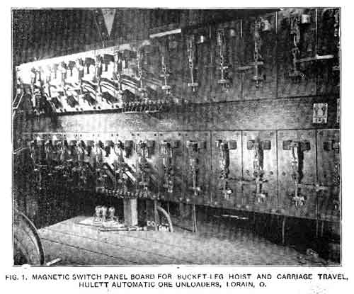
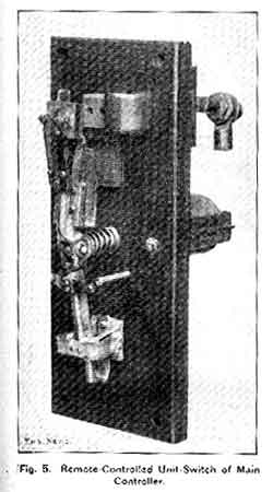
The main controllers of the Bucket-leg Hoist and Carriage travel are shown in the view Fig. 1 herewith. At the extreme right of the board are seen four pairs of switches, the two switches of each pair being interconnected by means of horizontal levers; these are the reversing switches and the function of the levers is to absolutely prevent the closing of the switches for opposite directions at the same time. At the left end of the board are three switches similarly interconnected by two levers; the function of these levers is (1) to prevent the closure of the middle or dynamic-breaking switch while the motor is still connected to the line and operating as a motor, and (2) to hold open the line switches (at either side of the center switch) while the motor is acting as a generator with the center switch closed. The intermediate magnet-switches control the connection of the resistances used in starting and in the automatic cut-out. Fig. 5 gives a view of one of the magnetic switch units of the controller.
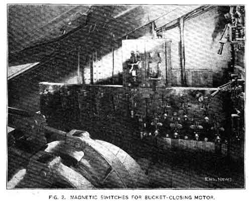
The bucket-closing motion, the motor for which is located on the rear end of the walking beam, is controlled by the switches shown in Fig. 2. The principal feature of this motion is the provision for automatic acceleration. Each switch magnet is so connected (electronically) to the magnet windings of the preceding switch that the current taken by the motor must fall to a predetermined value, after the closing of the preceding switch, before the switch can close. The smoothest possible acceleration, in the shortest time consistent with safety of motor and drive, is secured by this arrangement. Rapid throwing of the master switch cannot adversely affect the motor. The effect on the bucket mechanism is to make the motor drive almost precisely equivalent to steam or hydraulic drive; the motor will close the bucket at such a rate that a predetermined pressure on the bucket jaws is not exceeded. As a matter of fact, the motor is stalled on the average once during every closure of the bucket, and this occurs without injury to motor, controller, or operating mechanism. The automatic acceleration switches are at the right in the view Fig. 2. In the foreground is the electromagnetic band brake for holding the bucket in any given position.
The bucket rotation is controlled in only two steps, and, as it takes but a small current, a smaller and simpler form of magnetic switch unit is used for this motion.
The operation of the auxiliary hopper car is controlled by a switchboard similar to that shown in Fig. 1, but of fewer steps and therefore of more compact arrangement. The motor for this motion, and the panel board carrying the magnet switches, are located in the machinery house under the main carriage. The dumping of the car at the rear end of its travel is done by mechanical dogs.
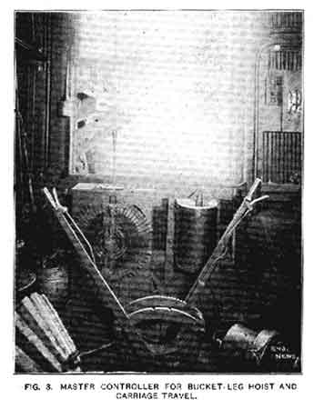
The type of master controller used in this equipment is exemplified by the bucket-carriage master controller, shown in Fig. 3. The manually operated controller seen at the left in this view controls a motor for slewing the entire machine, to bring it parallel to the hatches of the vessel. The dock is built on a large curve, which makes the motion necessary for best operation.
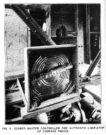
The mechanically geared automatic slow-down and cut-out for the main bucket carriage motion is shown in Fig. 4. This actuates appropriate magnet switches on the board shown in Fig. 1.
The control equipment described was designed, built and installed by the Electric Controller & Supply Co., of Cleveland, O., who also manufactured and supplied the cushion-type solenoids for the band brakes, and all other electrical details.